English


Sensors
General features
Magnetic sensors are devices that change circuit output status in the presence of magnetic fields.
They are normally used as proximity sensors on cylinders with a permanent magnet in the piston.
By positioning the sensor in a special housing on the outside of the cylinder body, the position of the piston can be detected via an electric contact or voltage signal.
The sensing element may be a reed switch or magneto resistive chip (GMR sensor) depending on the type of sensor.
Sensors are available with a cable outlet or connector.
A bespoke service is available if our standard products do not meet customer requirements.
Choosing a sensor
A sensor is a switch that is usually connected in series to a cable, therefore it must be installed in line with specified electrical characteristics.
There are two principles of operation:
-
a REED SWITCH where the sensing element consists of a glass bulb containing two polarised metal strips.
There is an attraction between these strips in the presence of a magnetic field.
It can operate with a DC or AC voltage supply.
The sensing element could malfunction in the presence of strong vibrations. -
ELECTRONICALLY where the sensing element is a magnetoresistive chip (GMR sensor), which changes the status of an output in the presence of magnetic fields.
It only operates with a DC voltage supply and has a theoretically infinite lifetime.
The sensing element is immune to strong vibrations.
The decision to choose a PNP or NPN output is usually determined by the method of integration in the existing automation sytem: for correct system operation, the type of sensor output must correspond to the type of controller (or PLC) output used.
The PNP solution is generally more widespread in North America and Europe, whereas the NPN solution is more common in Asia.
PNP sensors are vulnerable to short circuits, whereas NPN sensors can produce false signals in the controller in the event of an unwanted earth contact.
A final consideration is the status of the sensor under active conditions, i.e. between a normally open (NO) or normally closed (NC) sensor.
In the first case the sensor behaves according to positive sensing logic, a signal is not generated if a wire is interrupted but false signals may be produced in the event of a short circuit.
In the second case the sensor behaves according to negative sensing logic, and an interrupted wire would produce a false signal.
The logic can easily be inverted in both cases by the controller (or PLC).
Instruction on using magnetic sensors
Magnetic sensors are often used in combination with magnets to produce magnetic actuation, and are typically embedded in actuators.
The main characteristic of any digital sensor is the sensitivity level representing the magnetic field strength value at which the sensor switches the output.
The graph below shows the typical waveform of axial magnetic field strength measured by a Gauss meter in the central position (PC).
Depending on the sensitivity level of the sensor and magnetic field characteristics, a sensor placed centrally may switch output several times during the actuator stroke.
Unless started otherwise, it is generally good practice not to install the sensor centrally, but to insert it laterally into the groove and manually adjust the position of the sensor while performing several actuator strokes.
In pratice, sensors are normally only used to identify end-of-stroke conditions.
For any other operating conditions, please contact the technical support department.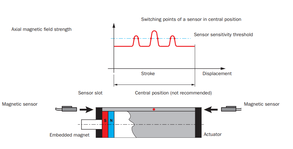
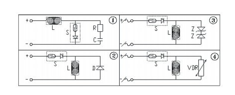
Sensor safety circuit
The switching of inductive loads with reed switches produces a high voltage peak during disconnection.
As a result, a safety circuit is required to prevent dielectric discharges or voltaic arcs.
This can be:
- A R-C circuit in parallel with the load in the case of a DC voltage supply (figure 1).
- A diode in parallel with the load in the case of a DC voltage supply (figure 2).
- 2 Zener diodes in parallel with the load with an AC/DC voltage supply (figure 3).
- A varistor (VDR) in parallel with the load with an AC/DC voltage supply (figure 4).
The switching of capacitive loads or the use of cables longer than 10 meters produces current peaks during connection.
As a result, protective resistance is required near the switch on the brown wire.
In this phase ensure the minimum current required for the sensor is guaranteed (10÷20 mA).